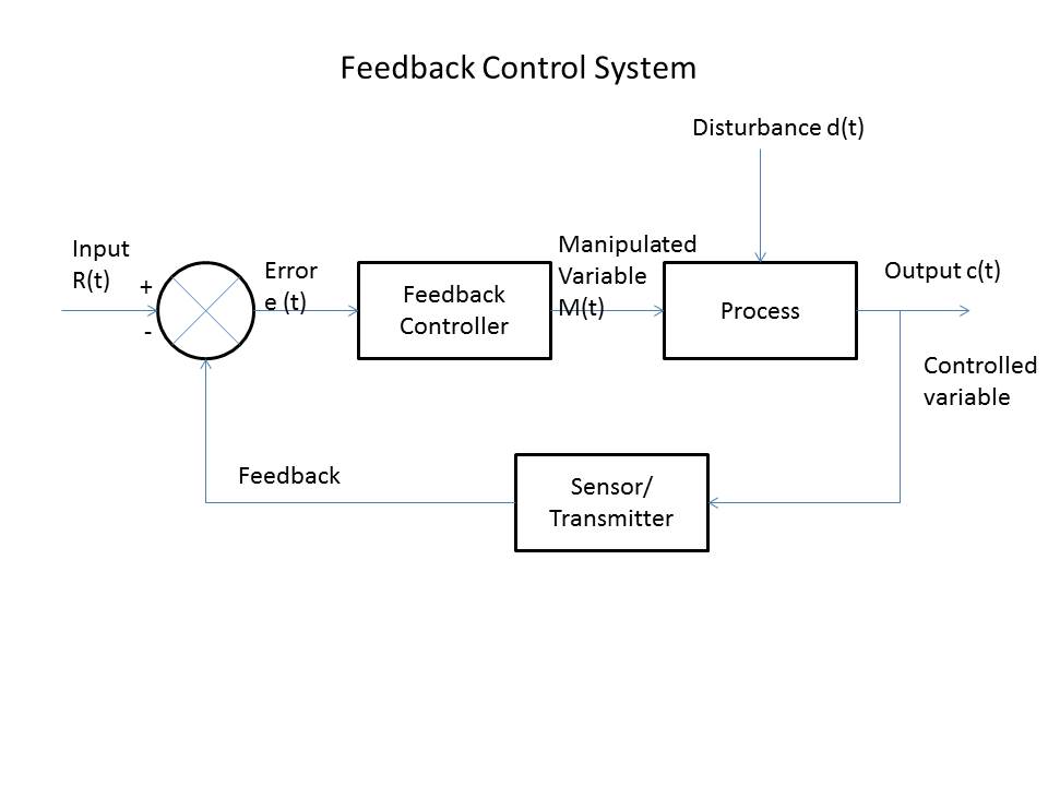
Feedback Control Circuit Diagram Solved: The Block Diagram O
Feedforward vs feedback control Inverter sg3525 sine circuits 3525 pwm battery watt 12v schematics sinewave 600va inversor correction rangkaian solar smps pcb diagrama skema Amplifier circuit – finding the negative feedback loop – valuable tech
12 Inverter with feedback control | Circuit projects, Circuit diagram
(a) electric feedback circuit diagram and (b) a block diagram of the Control speed motor circuit feedback seekic diagram Control system systems diagram block loop process closed controller error output feedback examples open pid negative general signal automatic engineering
Feedback sensory direct
Control feedback feedforward vs flow controller liquid level instrumentationtools scheme steam provide fig better belowFeedforward vs feedback control Inverter circuit with feedback control – homemade circuit projectsControl system basics.
Control system feedback loop closed output controller instrumentation example engineering error used signal input which reference explained two between becomesDiagram feedback block control system shown transfer following figure find chegg solved transcribed text show functions Feedback systemsDiagram block control process system feedback diagrams basics wiring motorcycle techtransfer flow drawing figure signals services sample technology.
Control systems
(pdf) design of microcantilever-based biosensor with digital feedback12 inverter with feedback control Feedback control circuitFeedback intelligent introduction instructor.
Control sensor transcribedThe basics of process control diagrams » technology transfer services Feedback control system or closed loop control systemWhat is a unity feedback loop and the core components of the system.

Feedback solved transcribed text
Potentiometer feedback linear actuatorActuator linear potentiometer arduino position controlling hardware overview firgelli schemas Solved the block diagram of a feedback control system isControl systems lecture: basic principles of feedback control – fusion.
Rc circuit block diagram with feedback in control engineering.Feedback control circuit diagram Feedback_controlFeedback control system-types and advantages.

Basic introduction to feedback control
Solved the block diagram of a feedback control system isSolved please give 5 examples of feedback control systems Biosensor microcantileverBlock diagram of feedback control system.
Circuit rc diagram block feedback controlOn-off control system – x-engineer.org Motor_speed_control_with_feedbackControl unity sensors kalman theory neuralink settling sensor throttle cybernetics input initial constant mpc components windbooster lag descriptions affecting fyi.

Typical block diagram of feedback control. sensory feedback has a
What is a feedback control system? types & advantagesFeedback control circuit System control block diagram feedback figure systems engineering diagrams sensor basics output controlledInverter circuits sg3525 sg3524 ic refer datasheets.
Feedback systemSolved: the block diagram of a feedback control system is Feedback control systems block diagram lecture principles basic approach figureBlock diagram of high voltage sampling feedback control circuit.

Solved (20pts) for the block diagram of feedback control
Control feedback circuit seekic automaticBlock diagram of process control system .
.


(a) Electric feedback circuit diagram and (b) a block diagram of the

Potentiometer Feedback Linear Actuator | FIRGELLI

Feedback control system or closed loop control system - Instrumentation

Block Diagram Of Feedback Control System

On-off control system – x-engineer.org

Control System Basics | Ledin Engineering, Inc.